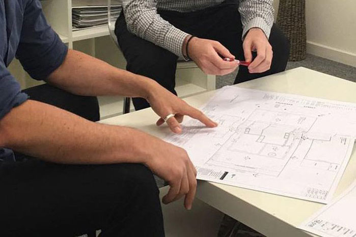
Undertaking a construction project of any kind requires professionals in various fields to join forces. By using building construction drawings, it ensures the experts know what they’re working on and how each part will come together to create the finished structure.
What are building construction drawings?
Construction drawings refer to visual sketches drawn digitally or by hand, laying out the proposed structure to be built. This may be for a residential, public or commercial building. In every construction drawing, you will find the dimensions, materials, notes and other important information. Usually architects and designers are the ones who draw up the construction drawings for a project, however, engineers and other professionals can also make drawings for larger projects.
Most drawings use standardised symbols and markings that are widely recognised across the industry, so construction teams and those who approve the permits, can easily read the plans. Construction drawings are also usually drawn to scale so that the dimensions of the actual proposed structure have been reduced down by equal amounts.
Types of construction drawings
There are various types of drawings that may be required in the construction process, they are listed below:
Site plans
This is a map of a construction site containing details about pre-existing structures on or close to the construction area, for example, roads and other buildings. You will also find topographical or natural elements (trees, foliage), and changes in land elevation. Site plans also include proposed changes to the location after construction, such as alterations to drainage systems or in topography.
Plot plans
Similar to site plans, plot plans show an above-ground or aerial view of the whole project site. The difference is that plot plans provide further information about where the building will be located, such as land survey marks. You will be able to determine the boundaries of structure as well as the property area, for example, you will be able to see that a building leaves room on the sides for grass.
Floor plans
With floor plans, you get a view of a construction building aerially, without a roof. Projects with more than 1 level will have a plan for each storey. You can expect to find specifications such as dimensions of both interior and exterior walls, purpose of each room, materials to be used, as well as stairs and its direction.
Excavation plans
These plans detail the dimensions (depth, width and length) of the excavation on the site and how it will occur (tunnelling or trenching).
Elevation drawings
This type of plan shows you the front vertical view of the proposed structure as if you were looking straight at it. Elevation drawings are 2D so they don’t depict a structure’s depth. These visuals sketch out the exterior view of the building including facade, roofing, fixtures and more. Measurements will also be detailed in the drawing such as distance between windows.
Section drawings
Similar to elevation drawings, section drawings show the vertical perspective of your project. However, they not only show what the building looks like from the outside, but they also allow you to see the hidden structures beneath the facade. For example, you can see the beams, columns, lintels, support structures, foundation of the building, and the insides of floors and walls.
Detail drawings
Detail drawings provide a clearer illustration of elements shown in other construction drawings but on a larger scale. For example, in regards to connections of various parts and placement. This can include elements such as staircases, door frames, window frames, cornices, decorative features and more.
Mechanical and electrical drawings
This type of drawing consists of the design and proposed location of power structures in the building. For example, air delivery rates, thermostat placements, load calculations, switch locations, wiring paths, connections to outdoor power grid and ductwork structures. If it is a very complex building, there may be separate drawings required, however, residential properties generally don’t need separate mechanical and electrical system drawings.
Plumbing and drainage drawings
This depicts the movement of water in and out of a building. Proper drainage systems ensure that those who live in the building in the future have access to safe water. You can find where water tanks, pumps, drains, pipes and vents are located in plumbing and drainage drawings.
Reflected ceiling drawings
Reflected ceiling drawings give a viewpoint of the ceiling from the floor, showing light fixtures, cornices and columns.
Perspective drawings
Perspective drawings are a 3d depiction of what the construction project will look like once completed. It helps builders visualise what they’re constructing.
Shadow diagrams
These diagrams are normally not required for the building process, however, will need to be submitted as part of the planning permit. Shadow diagrams show how the structure will cast shadowings onto neighbouring buildings at certain points of the day (varies based on the state you live in).
Which kind of drawings are required for your residential property project?
Residential homes normally require site plans, floor plans, elevation drawings, shadow diagrams and section drawings. Sometimes ceiling plans may be required if your home has more complex features or customisation.
Get in touch with the building and design experts at JKBD
JKBD is made up of a specialised team of residential designers. With decades of experience on hand, we know the ins and outs of the residential development process. We can help you every step of the way to ensure a successful outcome on your project, and especially in your building and construction documentation phase.
Reach out to our team for more information about our services.

